Pages

Monday

Top 10 common Software Architectural Patterns


Introduction:


Did you ever posed the question:  How large software in industrial scale systems are designed ?

Here I'll explain to you the most 10 common software architectural patterns one by one.

Before beginning the software development, we have to understand the requirement, then we have to choose a suitable architecture that will provide us the desired functionality and quality attributes.

What is the meaning of Architectural Pattern and why it's a very essential step ?

An architectural pattern is a general, reusable solution to a commonly occurring problem in software architecture within a given context. Architectural patterns are similar to software design pattern but have a broader scope.


1. Layered pattern:

This pattern can be used to structure programs that can be decomposed into groups of subtasks, each of them is at a particular level of abstraction. Each layer provides services to the next higher layer.

Layered pattern

As you can see in figure 'Layered pattern' The most commonly found 4 layers of a general information system are :

  1. Presentation layer (also known as UI layer)
  2. Application layer (also known as service layer)
  3. Business logic layer (also known as domain layer)
  4. Data access layer (also known as persistence layer)

The power of the layered architecture pattern is the separation of concerns among components which means that components within a specific layer deal only with logic that pertains to that layer.
This type of component classification makes it easy to build ,effective roles and responsibility models into your architecture, and also makes it easy to develop, test, govern, and maintain applications using this architecture pattern due to well-defined component interfaces and limited component scope.

The layered pattern architectures have been around since the beginning of digital computers (since the early 1960s), There is many examples of using this pattern in the systems you use every day, let's take for example the famous OSI seven-layer model that facilitates communication between computers. Here each layer provides a higher level of functionality than the layer below it


OSI model


2-Client-server pattern:

This pattern consists of two principal parties :a Server and multiple Clients.
The server component will provide services to multiple client components. Clients request services from the server and the server provides relevant services to those clients. Furthermore, the server continues to listen to client requests.
The most usage of this pattern is online applications such as email, document sharing and banking.

Client Server model


3-Master-slave pattern:

This pattern consists of two parties; master and slaves. The master component distributes the work among identical slave components, and computes a final result from the results which the slaves return.This pattern is often used for multi-threaded applications in which many instances of the same problem must be solved. (Travelling Salesman Problem, for example.) The master creates and launches slaves to solve these instances in "parallel". When all of the slaves have finished, the master harvests the results.
Master-Slave pattern is also used for user interfaces and servers. In both cases the master listens for commands coming either from the user or from clients. When a command is received, a slave is launched to execute the command while the master resumes listening for more commands (such as the "suspend the last command" command.)


Usage:
  • In database replication, the master database is regarded as the authoritative source, and the slave databases are synchronized to it. 
  • Peripherals connected to a bus in a computer system (master and slave drives).


4-Pipe-filter pattern:

This pattern can be used to structure systems which produce and process a stream of data. Each processing step is enclosed within a filter component. Data to be processed is passed through pipes. These pipes can be used for buffering or for synchronization purposes.
We use the Pipes and Filters architectural style to divide a larger processing task into a sequence of smaller, independent processing steps (Filters) that are connected by channels (Pipes).


In this pattern, a single event triggers a sequence of processing steps, each performing a specific function. For example, let's assume a new order arrives in our enterprise in the form of a message. One requirement may be that the message is encrypted to prevent eavesdroppers from spying on a customer's order. A second requirement is that the messages contain authentication information in the form of a digital certificate to ensure that orders are placed only by trusted customers. In addition, duplicate messages could be sent from external parties (remember all the warnings on the popular shopping sites to click the 'Order Now' button only once?). To avoid duplicate shipments and unhappy customers, we need to eliminate duplicate messages before subsequent order processing steps are initiated. To meet these requirements, we need to transform a stream of possibly duplicated, encrypted messages containing extra authentication data into a stream of unique, simple plain-text order messages without the extraneous data fields.

Usage:
  • Compilers. The consecutive filters perform lexical analysis, parsing, semantic analysis, and code generation.
  • Workflows in bioinformatics

5-Broker pattern:

This pattern is used to structure distributed systems with decoupled components. These components can interact with each other by remote service invocations. A broker component is responsible for the coordination of communication among components. Servers publish their capabilities (services and characteristics) to a broker.
Clients request a service from the broker, and the broker then redirects the client to a suitable service from its registry.

Broker pattern

Usage:
Message broker software such as Apache ActiveMQ, Apache Kafka, RabbitMQ and JBoss Messaging.


6-Peer-to-peer pattern:

In this pattern, individual components are known as peers. Peers may function both as a client, requesting services from other peers, and as a server, providing services to other peers. A peer may act as a client or as a server or as both, and it can change its role dynamically with time.


Usage: 
  • File-sharing networks such as Gnutella and G2) 
  • Multimedia protocols such as P2PTV and PDTP.

7-Event-bus pattern:

This pattern primarily deals with events and has 4 major components; event source, event listener, channel and event bus. Sources publish messages to particular channels on an event bus. Listeners subscribe to particular channels. Listeners are notified of messages that are published to a channel to which they have subscribed before.


Usage:
  • Android development 
  • Notification services
  • Dbus communication
8-Model-view-controller pattern

This pattern, also known as MVC pattern, divides an interactive application in to 3 parts as, 
  • Model: Contains the core functionality and data 
  • View:  Displays the information to the user (more than one view may be defined) 
  • Controller: Handles the input from the user. This is done to separate internal representations of information from the ways information is presented to, and accepted from, the user. It decouples components and allows efficient code reuse.


Usage:

  • Architecture for World Wide Web applications in major programming languages. 
  • Web frameworks such as Django and Rails.

9. Blackboard pattern:

This pattern is useful for problems for which no deterministic solution strategies are known. The blackboard pattern consists of 3 main components.

  • blackboard: a structured global memory containing objects from the solution space knowledge 
  • source: specialized modules with their own representation control 
  • component: selects, configures and executes modules.
All the components have access to the blackboard. Components may produce new data objects that are added to the blackboard. Components look for particular kinds of data on the blackboard, and may find these by pattern matching with the existing knowledge source.


The blackboard pattern provides effective solutions for designing and implementing complex systems where heterogeneous modules have to be dynamically combined to solve a problem. This provides non-functional properties such as:
  • Reusability
  • Changeability
  • Robustness.
The blackboard pattern allows multiple processes to work closer together on separate threads, polling and reacting when necessary.

Usage:
  • speech recognition
  • vehicle identification and tracking
  • protein structure identification
  • sonar signals interpretation.

10. Interpreter pattern

This pattern is used for designing a component that interprets programs written in a dedicated language. It mainly specifies how to evaluate lines of programs, known as sentences or expressions written in a particular language. The basic idea is to have a class for each symbol of the language. 


Usage:

Database query languages such as SQL parsing, symbol processing engine and languages used to describe communication protocols.


Comparison of Architectural Patterns :

The table given below summarizes the pros and cons of each architectural pattern:


MISRA is not everything! Another Embedded C Coding Standard is here

Barr Group‘s Embedded C Coding Standard

Barr Group‘s Embedded C Coding Standard becames one of the most interesting coding guide references in the embedded systems development. The book is known as “Barr Group‘s Embedded C Coding Standard“. A 2018 update to the book will be released soon and this will be the first time the substance of the standard has changed in over a decade.
The primary motivation for making changes is to better harmonize the rules with the MISRA-C Guidelines. The older Barr Group standard made reference to MISRA C:2004, which was superseded by MISRA C:2012. The few known direct conflicts between BARR-C:2013 and MISRA C (stemming from our earlier embrace of ISO C99) were effectively eliminated with their 2012 update. But Barr Group wanted to do more than just remove those noted conflicts and push even further in our embrace of harmonization.
In a sentence, MISRA C is a safer subset of the C language plus a set guidelines for using what is left of the language more safely. In about as many words, BARR-C is a style guide for the C language that reduces the number of defects introduced during the coding phase by increasing readability and portability. It turns out there is quite a bit of value in combining rules from both standards. For example, MISRA’s guidelines do not provide stylistic advice and applying BARR-C’s stylistic rules to the C subset further increases safety.
The rest of this post is a preview of the specific rule changes and additions we will make in BARR-C:2013. (Omitted from this list are rules reworded simply for greater clarity.)


link to the book : https://barrgroup.com/embedded-systems/books/embedded-c-coding-standard?utm=barrc_er


Saturday

Welcome in my blog

 Thank you for visiting my blog!

This blog is under maintenance and updates.


We will come back soon! 😄


Sunday

DĂ©tection d'Ɠil avec MATLAB 2016

La reconnaissance faciale par ordinateur:

La reconnaissance de visage est le processus d'identification d'une ou plusieurs personnes dans des images ou des vidéos en analysant et en comparant des modÚles. Les algorithmes pour la reconnaissance faciale extraient typiquement les caractéristiques faciales et les comparent à une base de données pour trouver la meilleure correspondance. La reconnaissance faciale est une partie importante de nombreux systÚmes biométriques, de sécurité et de surveillance, ainsi que des systÚmes d'indexation d'image et de vidéo.

Étapes du processus de reconnaissance de visage.


Notions de base


La détection d'objets à l'aide des classificateurs en cascade Haar est une méthode de détection d'objet efficace proposée par Paul Viola et Michael Jones dans son article "Détection Rapide d'Objets utilisant une Cascade de Fonctions Simples". Cascade est formée à partir d'un grand nombre d'images positives et négatives. Il est ensuite utilisé pour détecter des objets dans d'autres images.

Ici, nous allons travailler avec la détection de l'eye. Initialement, l'algorithme a besoin de beaucoup d'images positives (images des yeux) et d'images négatives (images sans yeux) pour former le classificateur. Ensuite, nous devons extraire des fonctionnalités de celui-ci. Pour cela, les caractéristiques de haar indiquées dans l'image ci-dessous sont utilisées. Ils sont comme notre noyau convolutionnel. Chaque caractéristique est une valeur unique obtenue en soustrayant la somme des pixels sous le rectangle blanc de la somme des pixels sous le rectangle noir.

DĂ©tection d'Ɠil a base de Matlab:


Eye detection using MATLAB


Code MATLAB:


faceDetector = vision.CascadeObjectDetector('C:\Users\Imed\Desktop\Projet_sign_detection_matlab\eye.xml');
pointTracker = vision.PointTracker('MaxBidirectionalError', 8);
cam = webcam();
videoFrame = snapshot(cam);
frameSize = size(videoFrame);

videoPlayer = vision.VideoPlayer('Position', [100 100 [frameSize(2), frameSize(1)]+30]);
runLoop = true;
numPts = 0;
frameCount = 0;
while runLoop && frameCount < 800
    videoFrame = snapshot(cam);
    videoFrameGray = rgb2gray(videoFrame);
    frameCount = frameCount + 1;

    if numPts < 10
        bbox = faceDetector.step(videoFrameGray);

        if ~isempty(bbox)
            % Find corner points inside the detected region.
            points = detectMinEigenFeatures(videoFrameGray, 'ROI', bbox(1, :));

            % Re-initialize the point tracker.
            xyPoints = points.Location;
            numPts = size(xyPoints,1);
            release(pointTracker);
            initialize(pointTracker, xyPoints, videoFrameGray);

            % Save a copy of the points.
            oldPoints = xyPoints;
            bboxPoints = bbox2points(bbox(1, :));

            % Convert the box corners into the [x1 y1 x2 y2 x3 y3 x4 y4]
            % format required by insertShape.
            bboxPolygon = reshape(bboxPoints', 1, []);

            % Display a bounding box around the detected face.
            videoFrame = insertShape(videoFrame, 'Polygon', bboxPolygon, 'LineWidth', 3);

            % Display detected corners.
            videoFrame = insertMarker(videoFrame, xyPoints, '+', 'Color', 'white');
        end

    else
        % Tracking mode.
        [xyPoints, isFound] = step(pointTracker, videoFrameGray);
        visiblePoints = xyPoints(isFound, :);
        oldInliers = oldPoints(isFound, :);

        numPts = size(visiblePoints, 1);

        if numPts >= 10
            % Estimate the geometric transformation between the old points
            % and the new points.
            [xform, oldInliers, visiblePoints] = estimateGeometricTransform(...
                oldInliers, visiblePoints, 'similarity', 'MaxDistance', 4);

            % Apply the transformation to the bounding box.
            bboxPoints = transformPointsForward(xform, bboxPoints);

            % Convert the box corners into the [x1 y1 x2 y2 x3 y3 x4 y4]
            % format required by insertShape.
            bboxPolygon = reshape(bboxPoints', 1, []);

            % Display a bounding box around the face being tracked.
            videoFrame = insertShape(videoFrame, 'Polygon', bboxPolygon, 'LineWidth', 3);
            position =  [1 50; 100 50];
value = [111 pi];text_str = 'eye';position =xyPoints;
box_color = {'red'};
hh=[bboxPoints(4,1) bboxPoints(4,2)];
videoFrame= insertText(videoFrame,hh,text_str,'FontSize',14,'BoxColor',...
    box_color,'BoxOpacity',0.6,'TextColor','white');
            % Display tracked points.
            videoFrame = insertMarker(videoFrame, visiblePoints, '+', 'Color', 'white');

            % Reset the points.
            oldPoints = visiblePoints;
            setPoints(pointTracker, oldPoints);
        end

    end

    % Display the annotated video frame using the video player object.
    step(videoPlayer, videoFrame);

    % Check whether the video player window has been closed.
    runLoop = isOpen(videoPlayer);
end

% Clean up.
clear cam;
release(videoPlayer);
release(pointTracker);
release(faceDetector);


Telechargement :

eye.xml 


Plus d'informations : imedelmottakel@gmail.com


Interfacing LCD with PIC Microcontroller – CCS PIC C


Je donne dans cet article une bibliothĂšque C pour les modules LCD basĂ©s sur le driver hd44780. Cette bibliothĂšque est Ă©galement disponible pour la famille de microcontrĂŽleurs AVR.  Cette bibliothĂšque est conçue pour ĂȘtre compilĂ©e et utilisĂ©e avec le compilateur CCS PIC C.


//LCD Module Connections
#define LCD_RS_PIN PIN_D1
#define LCD_RW_PIN PIN_D2
#define LCD_ENABLE_PIN PIN_D3
#define LCD_DATA4 PIN_D4
#define LCD_DATA5 PIN_D5
#define LCD_DATA6 PIN_D6
#define LCD_DATA7 PIN_D7
//End LCD Module Connections


Flex_lcd.c


//#define USE_RW_PIN   0      // donc't use RW PIN 
// These are the line addresses for most 4x20 LCDs. 
#define LCD_LINE_1_ADDRESS 0x00 
#define LCD_LINE_2_ADDRESS 0x40 
#define LCD_LINE_3_ADDRESS 0x14 
#define LCD_LINE_4_ADDRESS 0x54 
#define lcd_type 2   // 0=5x7, 1=5x10, 2=2 lines(or more) 
int8 lcd_line; 
int8 const LCD_INIT_STRING[4] = 
{ 
 0x20 | (lcd_type << 2),  // Set mode: 4-bit, 2+ lines, 5x8 dots 
 0xc,                     // Display on 
 1,                       // Clear display 
 6                        // Increment cursor 
 }; 
                             
//------------------------------------- 
void lcd_send_nibble(int8 nibble) 
{ 
// Note:  !! converts an integer expression 
// to a boolean (1 or 0). 
 output_bit(LCD_DB4, !!(nibble & 1)); 
 output_bit(LCD_DB5, !!(nibble & 2));  
 output_bit(LCD_DB6, !!(nibble & 4));    
 output_bit(LCD_DB7, !!(nibble & 8));    

 delay_cycles(1); 
 output_high(LCD_E); 
 delay_us(2); 
 output_low(LCD_E); 
} 

#ifdef USE_RW_PIN 
int8 lcd_read_nibble(void) 
{ 
int8 retval; 
// Create bit variables so that we can easily set 
// individual bits in the retval variable. 
#bit retval_0 = retval.0 
#bit retval_1 = retval.1 
#bit retval_2 = retval.2 
#bit retval_3 = retval.3 

retval = 0; 
    
output_high(LCD_E); 
delay_us(1); 

retval_0 = input(LCD_DB4); 
retval_1 = input(LCD_DB5); 
retval_2 = input(LCD_DB6); 
retval_3 = input(LCD_DB7); 
  
output_low(LCD_E); 
delay_us(1); 
    
return(retval);    
}    
#endif 

//--------------------------------------- 
// Read a byte from the LCD and return it. 

#ifdef USE_RW_PIN 
int8 lcd_read_byte(void) 
{ 
int8 low; 
int8 high; 

output_high(LCD_RW); 
delay_cycles(1); 

high = lcd_read_nibble(); 

low = lcd_read_nibble(); 

return( (high<<4) | low); 
} 
#endif 

//---------------------------------------- 
// Send a byte to the LCD. 
void lcd_send_byte(int8 address, int8 n) 
{ 
output_low(LCD_RS); 

#ifdef USE_RW_PIN 
while(bit_test(lcd_read_byte(),7)) ; 
#else 
delay_us(60);  
#endif 

if(address) 
   output_high(LCD_RS); 
else 
   output_low(LCD_RS); 
      
 delay_cycles(1); 

#ifdef USE_RW_PIN 
output_low(LCD_RW); 
delay_cycles(1); 
#endif 

output_low(LCD_E); 

lcd_send_nibble(n >> 4); 
lcd_send_nibble(n & 0xf); 
} 
//---------------------------- 

void lcd_init(void) 
{ 
int8 i; 

lcd_line = 1; 

output_low(LCD_RS); 

#ifdef USE_RW_PIN 
output_low(LCD_RW); 
#endif 

output_low(LCD_E); 

// Some LCDs require 15 ms minimum delay after 
// power-up.  Others require 30 ms.  I'm going 
// to set it to 35 ms, so it should work with 
// all of them. 
delay_ms(35);          

for(i=0 ;i < 3; i++) 
   { 
    lcd_send_nibble(0x03); 
    delay_ms(5); 
   } 

lcd_send_nibble(0x02); 

for(i=0; i < sizeof(LCD_INIT_STRING); i++) 
   { 
    lcd_send_byte(0, LCD_INIT_STRING[i]); 
    
    // If the R/W signal is not used, then 
    // the busy bit can't be polled.  One of 
    // the init commands takes longer than 
    // the hard-coded delay of 50 us, so in 
    // that case, lets just do a 5 ms delay 
    // after all four of them. 
    #ifndef USE_RW_PIN 
    delay_ms(5); 
    #endif 
   } 

} 
                                
//---------------------------- 

void lcd_gotoxy(int8 x, int8 y) 
{ 
int8 address; 


switch(y) 
  { 
   case 1: 
     address = LCD_LINE_1_ADDRESS; 
     break; 

   case 2: 
     address = LCD_LINE_2_ADDRESS; 
     break; 

   case 3: 
     address = LCD_LINE_3_ADDRESS; 
     break; 

   case 4: 
     address = LCD_LINE_4_ADDRESS; 
     break; 

   default: 
     address = LCD_LINE_1_ADDRESS; 
     break; 
      
  } 

address += x-1;                            
lcd_send_byte(0, 0x80 | address); 
} 
                                              
//----------------------------- 
void lcd_putc(char c) 
{                                    
 switch(c) 
   { 
    case '\f': 
      lcd_send_byte(0,1); 
      lcd_line = 1; 
      delay_ms(2); 
      break; 
    
    case '\n': 
       lcd_gotoxy(1, ++lcd_line); 
       break; 
    
    case '\b': 
       lcd_send_byte(0,0x10); 
       break; 
    
    default: 
       lcd_send_byte(1,c); 
       break; 
   } 
} 

//------------------------------ 
#ifdef USE_RW_PIN 
char lcd_getc(int8 x, int8 y) 
{ 
char value; 

lcd_gotoxy(x,y); 

// Wait until busy flag is low. 
while(bit_test(lcd_read_byte(),7));  

output_high(LCD_RS); 
value = lcd_read_byte(); 
output_low(LCD_RS); 

return(value); 
} 
#endif


Pour plus d'informations : imedelmottakel@gmail.com


Thursday

Application pour le calcul du bruit thermique


Bonjour tous le monde,

Dans ce monde, il n'y a pas de parfait ! Ce que mĂšne la vie dure aux traiteurs de signaux.
Car pratiquement il est impossible de trouver un signal parfait, ou signal sans
bruit.
Comme qu'il est un facteur trĂšs important dans la conception de nombreux appareils Ă©lectroniques / applications et circuits RF, il est important d'ĂȘtre en mesure de calculer les valeurs de bruit dans les conditions de travail de ces appareils..

Je m’intĂ©resse dans cette article au calcul du bruit Thermique 


PhénomÚne d'agitation thermique


Vous pouvez consulter Wikipédia pour plus d'informations a propos le bruit thermique.


Les calculs de bruit thermique peuvent ĂȘtre trĂšs utiles lors de la phase de conceptions des circuits Ă©lectroniques a faible puissance ou les circuits de haute frĂ©quence. Alors que certains intĂ©gration peut ĂȘtre nĂ©cessaire dans certains cas, il existe des Ă©quations simples pour la plupart des calculs requis.

Calcul du bruit thermique de base et les Ă©quations.

Le bruit thermique est un bruit blanc qui se trouve sur un spectre trÚs large. La puissance du bruit est proportionnel à la largeur de bande. Il est donc possible de définir une équation généralisée pour la tension de bruit à l'intérieur d'une bande passante donnée ci-dessous:


OĂč: 
V = tension efficace intĂ©grĂ©e entre les frĂ©quences f1 et f2 
R = composante rĂ©sistive de l'impĂ©dance (ou rĂ©sistance) Ω 
T = tempĂ©rature en degrĂ©s Kelvin 
(Kelvin est absolue Ă©chelle zĂ©ro donc Kelvin = Celsius + 273,16) 
f1 & f2 = inférieur et supérieur limites de la bande passante requise

Pour la plupart des cas, la composante rĂ©sistive de l'impĂ©dance reste constante sur la bande passante requise. Il donc possible de simplifier l'Ă©quation de bruit thermique Ă :

OĂč: 
B = largeur de bande en Hz

Calculs de bruit thermique pour la température ambiante

Il est possible de calculer les niveaux de bruit thermique pour la tempĂ©rature ambiante, 20 ° C ou 290 ° K. Ceci est le plus couramment calculĂ© pour une bande passante de 1 Hz, comme il est facile de mettre Ă  l'Ă©chelle Ă  partir d'ici en tant que puissance de bruit est proportionnelle Ă  la bande passante. L'impĂ©dance la plus courante est de 50 Ω.


Application développé:


Cette application permet de calculer la valeur estimé du bruit thermique dans une résistance.


Calculatrice du bruit thermique 


Vous pouvez tĂ©lĂ©charger cette application d'ici.


Plus d'informations: imedelmottakel@gmail.com


Friday

Comment mesurer des températures négatives avec un capteur LM35 et un PIC 16F877 ?


J'ai remarqué que la plupart des projets réalisés en titre "Projet Fin d'Etudes" ont une partie d'acquisition de la température.
La plupart entre eux oubliaient de mesurer la tempĂ©rature nĂ©gative ( tempĂ©rature < 0 °C ) ce que provoque un mal-fonctionnement en hiver.
Je veut présenter par cet article comment mesurer une température négative en utilisant le célÚbre capteur LM35 et un microcontrÎleur PIC 16F877.


Le capteur LM35 supporte des tempĂ©ratures assez extrĂȘmes (jusqu'Ă  -55°C / +150°C), mais il n'en est pas de mĂȘme pour les microcontrĂŽleurs PIC.

Si vous soumettez un microcontrĂŽleur PIC "classique" Ă  ces tempĂ©ratures extrĂȘmes, elle va purement et simplement cesser de fonctionner ou se dĂ©grader trĂšs rapidement. Cela est valable pour les microcontrĂŽleurs PIC, mais aussi pour tous autres circuits Ă©lectroniques fabriquĂ©s suivant les standards "grand public" (et non "industriels").
Pour information, les gammes de températures classiques en électronique sont les suivantes :
  • grand public : 0°C ~ 70°C 
  • industrie : -40°C ~ 85°C 
  • militaire : -55°C ~ 125°C

Mesurer des températures négatives


Le montage


Pour réaliser ce montage, il va nous falloir :


  • Un microcontrĂŽleur PIC 16F877 
  • Un capteur LM35 (attention, il faut bien prendre une version CZ ou CAZ, pas DZ !) 
  • Un condensateur de 100nF (optionnel, mais recommandĂ©) 
  • Deux diodes 1N4148 
  • Une rĂ©sistance de 18K ohms (marron / gris / orange
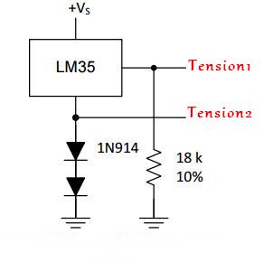
Montage du capteur LM35 pour mesurer une température négative

Le principe 


Les deux diodes 1N4148 induisent une chute de tension d'environ +0.6 volt à leur borne chacune (c'est une caractéristique physique des diodes, appelée "Forward Voltage", soit +1.2 volt au total entre la masse réelle du montage et la broche GND du capteur.

Avec une masse à +1.2 volt au niveau du capteur, il est possible pour le capteur d'aller en dessous de "leur" 0 volt vu qu'il n'est pas en réalité à 0 volt, mais à +1.2 volt.

Il y a cependant un petit souci avec ce montage : la tension aux bornes des diodes varie en fonction de la tempĂ©rature … Ce qui est embĂȘtant pour un montage censĂ© mesurer des tempĂ©ratures. C'est un comportement normal pour une diode, c'est mĂȘme un comportement qui est utilisĂ© pour mesurer des tempĂ©ratures. Sauf que dans notre cas, c'est un comportement parasite.

L'astuce pour "Annuler" cette variation de tension parasite en fonction de la température consiste à mesurer la tension au niveau de la broche GND du capteur, puis de corriger la mesure finale en faisant une soustraction dans le code pour les mésures.


Vue schématique du montage et code:


Pour commencer notre montage, nous allons cùbler la broche VCC du capteur à l'alimentation 5V. On relie ensuite la broche GND du capteur en série avec les deux diodes 1N4148, puis à la broche GND.

N.B. Les diodes sont polarisées ! Elles ont un "sens". Le trait noir sur la diode indique l'emplacement de la barre verticale sur le schéma.

On continue le montage en reliant la broche GND du capteur (juste aprĂšs les deux diodes), Ă  la broche Ra0 de PIC.

Toujours pour faire les choses bien, on va venir cĂąbler un condensateur de 100nF entre les broches VCC et GND du capteur. Il faut que le condensateur soit cĂąblĂ© le plus prĂšs possible du capteur pour ĂȘtre efficace.

On termine en reliant la sortie du capteur à la broche Ra0 avec un fil et en cùblant la résistance de 18K ohms entre la sortie du capteur et la broche GND.


Le code


=> Code C pour CCS PIC C Compiler V4.12

Le code complet avec commentaires :
 
#include <16F877.h>
#device adc=10
#FUSES NOWDT                    //No Watch Dog Timer
#FUSES HS                       //High speed Osc (> 4mhz for PCM/PCH) (>10mhz for PCD)
#FUSES NOPUT                    //No Power Up Timer
#FUSES NOPROTECT                //Code not protected from reading
#FUSES NOBROWNOUT               //No brownout reset
#FUSES NOLVP                    //No low voltage prgming, B3(PIC16) or B5(PIC18) used for I/O
#FUSES NOCPD                    //No EE protection
#FUSES NOWRT                    //Program memory not write protected
#FUSES NODEBUG                  //No Debug mode for ICD
#FUSES RESERVED                 //Used to set the reserved FUSE bits
#use delay(clock=20000000)
#use rs232(baud=9600, xmit=PIN_C6,rcv=PIN_C7, timeout=2000)  
#include <math.h> 
#define LCD_ENABLE_PIN  PIN_B0                                    ////
#define LCD_RS_PIN      PIN_B1                                    ////
#define LCD_RW_PIN      PIN_B2                                    ////
#define LCD_DATA4       PIN_B4                                    ////
#define LCD_DATA5       PIN_B5                                    ////
#define LCD_DATA6       PIN_B6                                    ////
#define LCD_DATA7       PIN_B7  
#define LCD_TYPE 2
#include "LCD420.C" 
#include <string.h>
#include <stdlib.h>
#include <ctype.h>
#include <stdio.h>

void main()
{  
lcd_init();
setup_adc_ports(AN0_an1_an3);
setup_adc(ADC_CLOCK_DIV_8);
delay_us(20);

while(1){
set_adc_channel(0); // calculer tension1
delay_ms (10);
int16 tension1 = read_adc();
set_adc_channel(1); // calculer tension2
delay_ms (10);
int16 tension2 = read_adc();
signed int16 temperature = tension1 - tension2; // mesurer la difference
lcd_gotoxy(1,1);
printf(lcd_putc,"temp= %2.1f",temperature*5.*100./1023.); // afficher la temperature
lcd_putc(223); //afficher la signe du C
printf(lcd_putc,"C   ");
}}//end void main() 

Le résultat


Simulation du circuit : PIC 16F877 + LCD + LM35 (tempĂ©rature nĂ©gative)


Simulation du circuit : PIC 16F877 + LCD + LM35 (tempĂ©rature positive)


Conclusion


Il faut toujours penser Ă  faire une circuit Ă©lectrique qui fonctionne dans tous les conditions climatiques.

N'oublier jamais la signe "-"  pour l'unitĂ© °C !


=> Plus d'informations : imedelmottakel@gmail.com
=> https://www.facebook.com/Imed.Elmottakel


Top 10 common Software Architectural Patterns

Introduction: Did you ever posed the question:  How large software in industrial scale systems are designed ? Here I'll explai...